Presented at the 29th Annual International Conference on Soils, Sediments, Water, and Energy, UMASS at Amherst
ABSTRACT
Environmental regulators increasingly prefer in situ remediation technologies and active vapor intrusion (VI) mitigation. Vapor mitigation and in situ source removal represent the primary concern at sites where water table or vadose zone hydrocarbon volatilization can affect indoor air quality.
Horizontal directional drilling (HDD) technology and engineered horizontal well screens are applied at sites where in situ remediation strategies and/or VI drive site closure strategy. Where chlorinated solvents are the issue, horizontal wells enable soil vapor extraction (or multiple in situ chemical oxidation injections) and provide subslab depressurization with appropriately sized/controlled blower systems.
Free phase light non-aqueous phase liquid (LNAPL) accumulations can pose significant in situ remediation challenges. Vertical wells cannot supply sufficient oxygen to maintain vigorous bacteria populations required for successful biosparging and free phase biosparging is generally not considered feasible. However, horizontal well screens and blower systems for biosparging have been successfully applied at a site with thousands of gallons of free product.
HDD coupled with engineered horizontal well screens are used to reach inaccessible locations and achieve site closure more rapidly than vertical technology. Horizontal screens hundreds of feet long are installed beneath structures and other locations inaccessible to vertical equipment. More rapid site closure is achieved via two principal factors: zone of influence (ZOI); and the stratified nature of typical target zones of sedimentary origin. Horizontal screens develop significant elliptically-shaped ZOI. Vertical anisotropy resulting from the sedimentary stratification causes channeling and impedes fluid flow through the porous formation to the vertical screen in the most efficient pattern, producing the greatest rate of pore volume exchange. Horizontal screens placed largely within a single sedimentary unit will develop the most efficient flow pattern within that sedimentary unit.
INTRODUCTION
Remediation professionals have for many years used horizontal remediation wells (HRWs) to successfully address technically challenging problems such as: 1) employing air sparge or biosparge/soil vapor extraction (AS/SVE) remediation to large subsurface LNAPL releases; 2) vapor intrusion mitigation beneath occupied commercial structures; 3) reaching inaccessible contaminant masses located beneath structures and civil infrastructure; and 4) dependably achieving rapid site closure.
MATERIALS AND PROCEDURE
Horizontal directional drilling technology was developed for the oil and gas industry to enhance recovery and more recently employed along with hydraulic fracturing to produce hydrocarbons from shale formations. The technology was subsequently adapted for shallow applications including subsurface utilities, such as fiber optic cable installation beneath roads.
Horizontal drilling technology employs specialized drill rigs, high tensile strength tubulars, special drill bits and battery operated sonde and locator instruments. A HDD drill rig is compact, maneuverable, capable of exerting considerable hydraulic horizontal thrust and designed for robust production rates, enabling the driller to operate the rig from a console without manually manipulating tubulars.
Directional Technologies began designing and installing horizontal remediation wells (HRWs) over 20 years ago. Well materials used in HRWs include polyvinyl chloride (PVC), high density polyethylene (HDPE), fiberglass reinforced epoxy (FRE) and stainless steel. The driller has two options for HRW installation: continuous (entry-exit) well and blind (no exit) well. For a continuous well, the drill bit enters the ground, reaches a specified target depth, breaches the surface (“daylights”) and the riser and screen are pulled into the bore. For a blind well, the drill bit enters the ground, reaches the specified target depth, the drill bit is withdrawn and the screen and riser are pushed into position. Blind wells are very useful where surface space is limited or there is no real estate in which to daylight.
Horizontal well screen design is critical to successful HRW performance. In other words, it is essential that the screen provide uniform flow (or vacuum) across the entire screen length. Directional Technologies Inc. achieves screen design uniformity by using hydrogeologic software to model fluid flow through the riser, screen slots and into/through the formation.
Directional Technologies Inc. regularly mitigates VI by installing HRWs under buildings to depressurize the floor slabs. In many cases one HRW is sufficient to depressurize the entire slab. A significant advantage afforded by this technology is that the HRW can be installed in occupied buildings without enduring costly business interruptions. Vapor intrusion mitigation HRWs can be designed to also efficiently distribute in situ chemical oxidation (ISCO) reagents or bioamendments for enhanced biodegradation of contaminants within target soil volumes that are either too large or inaccessible for vertical injection methods to be successful.
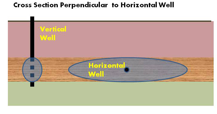
Conventional wisdom teaches that biosparging technology is ineffective at sites with significant free phase LNAPL accumulations because subsurface oxygen concentrations cannot be adequately maintained to sustain bacteria populations that use LNAPL as a nutrition source. Owing to substantially greater screen length, HRW screens provide significantly greater contact area with impacted media than vertical wells. This concept is illustrated in Figure 1.

A horizontal screen delivers remediation amendments into an LNAPL-impacted soil horizon evenly, as a line source, which is much more effective than the point sources provided by a series of vertical wells. This difference enables HRWs to be successfully used for biosparging.
A retail petroleum site in New England experienced gasoline releases from underground storage tanks (USTs) in the 1990s. The USTs were replaced but only some impacted soil was removed and replaced with clean fill. The remaining impacted soil re-contaminated the clean fill and groundwater. Analysis confirmed that an air sparge/soil vapor extraction (AS/SVE) system using HRWs would be significantly less expensive to install than one using vertical wells. This is because the HRWs avoided costly “soft dig” techniques for trenches required of the vertical system for interconnecting piping installation. In addition, HRW installation avoided the prohibitive cost of interrupting the normal operations of the business.
During preparation of the site’s remediation feasibility study, it was estimated that a vertical well-based AS/SVE system would require 3-5 years of operation and maintenance (O & M) to achieve closure numerical criteria. The HRW-based AS/SVE system only operated for approximately 1 year when closure criteria were achieved.
DATA AND ANALYSIS
Directional Technologies Inc. installed a network of parallel HRWs (four [4] AS and three [3] SVE) approximately 600 feet long to remediate a large subsurface gasoline release at an international airport in 2011. Horizontal wells were selected because of severe site constraints, the release magnitude and aerial extent—thousands of gallons and multiple acres, respectively and the need to remediate the site quickly. The wells were constructed of four (4)-inch diameter SDR-11 high density polyethylene (HDPE).
Various tests were performed after well installation and during operation in 2012 to determine HRW performance parameters. Pressure readings were recorded for air pressure exerted on the AS wells and a summary for AS well HAS-2 is presented in Table 1.
Table 1. HAS-2 Pressure/Air Flow Summary, May-September 2012 | Wellhead Pressure (PSI) | Wellhead Pressure (in. WC) | Sparge Well Air Flow (ACFM) | Sparge Well Air Flow (SCFM) |
5/17/2012 | 7 | 193.9 | 152.7 | 216.9 |
6/1/2012 | 7 | 193.9 | 209.4 | 303.1 |
6/15/2012 | 7.5 | 207.8 | 218.2 | 321.7 |
6/30/2012 | 7.25 | 200.8 | 218.2 | 308.8 |
7/15/2012 | 7 | 193.9 | 218.2 | 307.6 |
7/31/2012 | 7.5 | 207.8 | 261.8 | 376.9 |
8/15/2012 | 7 | 193.9 | 261.8 | 371.8 |
8/31/2012 | 7 | 193.9 | 244.3 | 344.6 |
9/13/2012 | 7.25 | 200.8 | 261.8 | 372.6 |
The summary shows that air pressure is measured immediately at system start-up along the entire well screen, demonstrating how effective HRWs are compared with vertical wells. This can be attributed to substantially greater screen length and impacted media contact area than a vertical well (as discussed in Section 2.2) and significantly greater zone-of-influence (ZOI) compared with vertical wells.
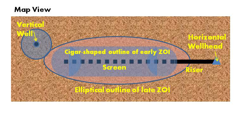
Initially after startup, a horizontal well will have a ZOI that is cigar shaped around the screen (see Figure 2), with a capture zone about as wide as the zone of influence measured in a vertical well test in the same formation.

Unlike the vertical well, which will reach its maximum ZOI relatively quickly, with little variation along its comparatively short screen, the horizontal well’s ZOI will gradually develop into an elliptical shape, with the screen endpoints defining the focal points of the ellipse. The distance to the edge of the ZOI will be greatest at the well’s midpoint. Only at the screen endpoints will the horizontal well’s ZOI be similar to that of a vertical well in the same formation. The HRW’s ZOI will typically exceed that of a vertical well along most of the horizontal screen. Our experience shows that the horizontal well screen ZOI is usually many times greater than a corresponding vertical well screen in the same formation. For example, the HRWs installed at the aforementioned airport have a ROI of at least 30 feet on either side of the screen. We have HRWs operating in industrial VI mitigation systems with ROI exceeding 200 feet.
This ZOI shape difference is due to two main factors. One is simply the screen length, which is too short in the vertical well for the elliptical shape to present much change in the distance to the edge of the ZOI along the screen. The other is the stratified nature of typical target zones of sedimentary origin. Vertical anisotropy resulting from the stratification causes channeling and impedes fluid flow through the porous formation to the vertical screen in the most efficient pattern, producing the greatest rate of pore volume exchange. A horizontal screen placed largely within a single sedimentary unit will develop the most efficient flow pattern within that sedimentary unit.
These aforementioned factors explain why HRWs usually significantly outperform vertical wells in the same formation. For example, daily volatile organic compound (VOC) recovery rates (in pounds [lbs.] per day) for SVE well HSVE-2 at the aforementioned airport site for the first six months of 2012 are presented in Table 2.
Table 2. HSVE-2 Vacuum, Air Flow and VOC Recovery Summary January – July 2012 | Wellhead Vacuum (in. WC) | Air Flow (SCFM) | VOC Concentration (ppmv) | VOC \Recovery Rate (lbs./day) | Cumulative VOCs Recovered (lbs.) |
1/25/2012 | 14 | 119 | 1,256 | 192 | 1,041 |
2/29/2012 | 32 | 209 | 1,300 | 297 | 10,665 |
3/31/2012 | 24 | 166 | 1,270 | 261 | 18,339 |
4/22/2012 | 52 | 273 | 1,197 | 252 | 24,080 |
5/21/2012 | 56 | 175 | 1,197 | 174 | 25,154 |
7/11/2012 | 20 | 304 | 1,173 | 320 | 25,291 |
7/16/2012 | 40 | 317 | 509 | 235 | 26,687 |
The VOC recovery rates range from 174 to 320 lbs. per day, with a cumulative VOC recovery of 26,687 lbs. over six months. These performance results were achieved by a single well, indicating that the full-scale horizontal well system will achieve site closure much more rapidly than any equivalent vertical well system.
CONCLUSION
Directional Technologies Inc.’s horizontal directional drilling experience coupled with its expertise in engineered well screen design and horizontal well installation technology has a decade-long successful track record. This technology coupling provides unique capabilities related to site/structure access, business disruption avoidance, accelerated site closure and enhanced site safety. Horizontal remediation well technology is proven and has been successfully used for over 25 years. Horizontal remediation wells have consistently outperformed vertical wells because they provide an effective delivery mechanism to reach previously inaccessible remediation targets, enable targets beneath buildings to be remediated without disrupting business operations and usually result in more rapid site closure, providing a superior option for cost-effective site remediation.