Challenge
Remediate a plume of trichloroethylene (TCE) under multiple military buildings by two types of horizontal remediation wells: air sparging (AS) and soil vapor extraction (SVE). There are two target zones: the shallow zone is approximately 70′ below grounds surface (bgs) and 20′ below that is the deep zone.
The plume was located under multiple buildings comprising an area of approximately 150,000 SF. Horizontal Remediation Wells installed by experienced environmental directional drillers was chosen because the remediation system could be installed without interruption to the activities in the buildings and because the system could be installed without access to the building therefore maintaining the integrity of the military security for this project.
Scope of Work
Install three AS and one SVE wells using horizontal directional drilling methods in the overburden material (sapprolite).
Engineering Goal: The primary engineering goal is to achieve uniform injection of air along the screened sections of the horizontal remediation wells, given site-specific hydrogeologic and hydraulic characteristics as well as the intended operating conditions of the compressor system. For this reason a design report was provided with specific slotting instructions for the horizontal remediation wells. The program simulates air moving down the well, through the slots and into the formation. The results are then used to determine the amount of open area along the screen and whether slot size needs to vary along the length of screen in order to maintain uniform flow.
Design: Each of the three horizontal remediation wells was designed to specific details. All horizontal remediation wells were to be drilled from north to south, entry and termination points were established, elevations of screen termination were defined. 4″ diameter schedule 10 stainless steel was recommended in order to withstand well installation stresses however the SVE well was constructed with 6-inch SDR-11 HDPE pipe. The open areas along the screens were determined for each well and were uniform along the length of all horizontal well screens. Blind end AS wells were required due to military security and the inability to enter the structures whereas the owner specified a double ended SVE well.
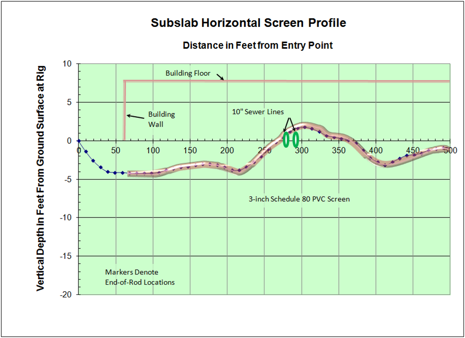
Installation: Two horizontal remediation wells , AS-A and AS-C, were installed in the shallow zone which was characterized by fine silty sands to silty sandy clay. The screens of the wells AS-A and AS-C are at at depth of approximately 45-55′ at the point of entry to 70′ at the southern end.
A third horizontal remediation well, AS-B was installed in the deeper zone. This zone was characterized by fine clayey sands and silts. The depth of the screen is 75′ at the entry point to 90′ for most of the southern half of the screen. The screen length of each of these wells is approximately 500′. Setback distances were specified by the owner for these wells and were 350′, 400′ and 350′ respectively. Set back distances were established due to the depth of the proposed screen sections, the presence of buried utilities and infrastructure in the area and the proposed location of the equipment compound. Groundwater elevations are expected to be fairly constant; screens of AS-A and AS-C will be subjected to an average groundwater head of 40′ while that of AS-B will be subjected to an average of 61′ of head.
A 6″ SDR-11 HDPE vapor extraction well, VE-A, was installed 42.6′ above AS-A this corresponds to depths ranging between 16 and 27′ bgs along the screened section. It is designed to extract air in the vadose zone immediately above AS-A. The SVE well screen extends an additional 80′ beyond the underlying air sparge screen. Soils in this area were fine silty sands with some clay to find sandy clay with some silt. This well has an exit point with a riser on either end. The screen length for this well is 600′, with a setback distance of 300′.
The bore paths were guided using an ultra-deep wire-line sonde, which transmits a signal to the surface for directional control. Upon completion of the bore the data is entered into a computer for the generation of as-built drawings. As per our standard procedure, well development began immediately upon well installation. Development water was treated on-site using an existing treatment system. The project was completed on time and within the owner’s specifications.
