Post-Closure Analysis Proves Success of Enhanced Hydrocarbon Bioremediation Using Twelve Horizontal Sparge Wells at Petroleum Projects Bulk Terminal
Michael Sequino, Directional Technologies, Inc., James R. Oppenheim. Sunoco, Inc., and Kevin W. Martin, CHMM, Aquaterra Technologies, Inc
Introduction
A major oil storage facility (MOSF) in New York was successfully remediated in the late 1990’s using a horizontal well air sparge system. The site is closed and no remedial efforts have been required since 2003. The subject property is known as Griffith Terminal, (“site”) located on the south side of Route 352 in Big Flats, Chemung County, NY. Elevated concentrations of dissolved phase hydrocarbons were detected in site groundwater monitoring wells in 1995. Non-aqueous phase liquids (NAPL) were subsequently discovered in the vicinity of a six-inch diameter petroleum product pipeline that passed under Route 352. Product inventory records indicated that approximately 50,000 gallons of product were released between 1994 and 1995, including mixed oils, gasoline, No.2 fuel oil and kerosene. The plume related to the product release encompassed approximately 15 acres. Sensitive receptors include residences with private wells, the Chemung River, and a quarry with a pond. The objectives were to prevent exposure to sensitive receptors, control the plume by preventing migration beyond the existing plume boundaries, and remediate the plume using a logical, phased implementation of the remediation program.
Site Location & Description
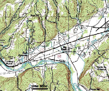
The subject property is known as Griffith Terminal (“site”) encompassing approximately 20 acres, located on the south side of Route 352 between the intersections of South Corning Road and Route 17 in Big Flats, Chemung County, NY. The site’s elevation is approximately 900 feet above mean sea level. The surrounding area has low topographic relief, with a shallow slope southeast toward the Chemung River, which flows adjacent to the site along the south and southeastern property boundaries. Surrounding land use includes residential properties, light commercial properties and an industrial property (Figure 1).
Description of Facility
The site is a major oil storage facility (MOSF), containing several slab-on-grade buildings, a product loading rack and six aboveground bulk petroleum storage tanks (AST) located in the approximate center of the site. The site also contains two 30,000-gallon bulk propane ASTs located in the southern portion of the site on what used to be known as the Stueben property. Approximately 15% of the property is covered by impermeable surfaces while the remainder is covered with gravel or turf (Figure 1).
Figure 1: Site Location Map

Site Hydrogeology
The Corning Elmira Primary Aquifers, consisting of highly permeable gravel deposits, exist beneath the site. A constant rate 24-hour pumping test performed at a constant rate of 14 gallons per minute revealed calculated hydraulic parameters including transmissivity of 13,000 gallons per day per foot, storativity of 0.02 and hydraulic conductivity of 210 gallons per day per square foot, which is equal to 28.1 feet per day.
Groundwater depth varies between 9 and 17 feet across the site. Historical groundwater monitoring well data indicate that the site water table is subject to seasonal fluctuations of approximately four feet. Groundwater flow is predominantly southeast toward the Chemung River (Figure 2).
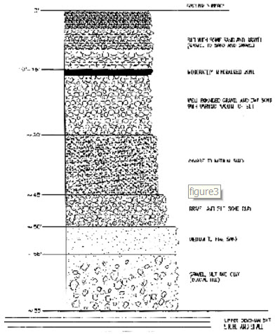
The site bedrock consists of the West Falls Group comprised of Devonian shale and siltstone. Overburden soils consist of approximately 65 feet unconsolidated glacial and fluvial deposits. Logs for groundwater monitoring, recovery, soil vapor extraction and sparge wells installed post-release indicate that silt and fine-grained sands are present at the surface, grading to well-rounded gravel and sand at 10-15 feet below ground surface (bgs). The sand and gravel layer is approximately 15-feet thick and is underlain by coarse to medium sand. A confining layer of silt and gravel is present at approximately 45 feet bgs and a second confining layer of glacial till overlies the bedrock (see Figure 3).
The recharge and product yield obtained from monitoring wells is highly variable due to the presence of zones of highly transmissive stringers or buried erosional channels which may or may not intersect the boring depending on location. It is impossible to predict the location of such zones when advancing vertical borings.
Figure 2: Site Map with Potentiometric Surface Contours

Figure 3: Stratigraphic Column

Site History
Elevated concentrations of dissolved phase hydrocarbons were detected in site groundwater monitoring wells in May 1995. This discovery triggered an investigation and non-aqueous phase liquids (NAPL) were subsequently discovered in the vicinity of a six-inch diameter product delivery pipeline that crossed under Route 352 during July 1995 (see Figure 1). The product delivery pipeline reportedly exhibited corrosion when inspected. A NAPL sample was collected and analyzed and found to be less than one year old. The greatest NAPL thickness of 2.3 feet was detected in monitoring well MW-21 in 1995. It was estimated that at least 50,000 gallons of petroleum products were released to the subsurface between 1994 and 1995. Product lost during this period included mixed oils, gasoline, No. 2 fuel oil and kerosene. An eight-inch diameter pipeline was subsequently installed to replace the six-inch pipeline.
Remedial Actions
A series of remedial actions have been implemented, including excavation, soil vapor extraction, air sparging, oil skimming and total fluids extraction using vertical wells, air sparging with horizontal wells, and wellhead treatment of water supply wells. Only the wellhead treatment is ongoing.
A combination of floating skimmers, an automatic product-only pump, an auto-skimmer, hand bailing and vacuum enhanced pumping were employed to recover NAPL from July 1995 to August 1995. Sixty tons of soil were excavated in 1996. A total phase extraction system was also installed, connected to monitoring wells MW-10, 15, 16, 17, 33 and 42 and operated from 1999 and 2000 during low water table conditions (late summer through early fall). Approximately 19,000 gallons of SPH was recovered using these combined technologies.
Conceptual Site Model
The primary means of groundwater and contaminant mobility is through buried channels of transmissive sand and gravel. Boring logs show sand and gravel lenses interbedded with less permeable silty and clayey soils. A poorly cemented bed of gravel, sand and silt occurs at 10 to 15 feet bgs and appears to act as a barrier to vertical movement of soil vapor.
The groundwater gradient is eastward toward the quarry. Groundwater fluctuates about 4 feet, creating a substantial smear zone. Free product has collected in the smear zone. This makes the subsurface amenable to air sparging and soil vapor extraction. In addition the site has a dissolved groundwater plume.
Vapor phase contamination is present throughout the area defined as underlain by free product. Lateral migration of soil vapor contamination is limited. Soil vapor contamination does not appear to extend beyond the dissolved contaminant plume.
Remedial Objectives
The plume related to the product release initially encompassed approximately 15 acres (see Figure 2). The most significant sensitive receptor is the Chemung River, adjacent to and hydraulically downgradient of the site.
Private commercial and residential wells have documented petroleum impact, including toluene, MTBE, and ethylbenzene, and are operating with point of entry treatment systems.
The site remediation objectives were to:
- Prevent impacts beyond known plume boundaries; and
- Aggressively remediate the plume in a step-wise phased approach:
- Limit the migration of product and dissolved plume to the potential receptors including potable drinking water wells in the vicinity, the quarry to the east, and the Chemung River.
- Remove free product
- Remediate soil and groundwater to established site-specific cleanup levels required by NYSDEC
Remediation Strategy
The horizontal wells were installed as part of a large field-scale program to address the groundwater plume by removing source area contaminant mass, decreasing the area of the plume that exceeds regulatory standards, promoting natural attenuation. Plume stability is the expected result of attainment of these remediation goals. Engineering analysis revealed that a total of 129 vertical wells coupled with 23 blowers would be required to remediate the entire affected area via bio-sparge technology. Analysis further revealed that only 12 horizontal bio-sparge wells coupled with 6 blowers would be required to remediate the same area. As a gross approximation the time and cost of a remedial project such as this is inversely proportional to the amount of well screen that can be placed in contact with contaminated media. For this project, the vertical well system would provide only 272 feet of well screen versus 2,650 feet of well screen for the horizontal well system. On a generalized basis it can be stated that horizontal well installation costs are greater than vertical wells; however, when assessing total life cycle costs, horizontal well systems are substantively less expensive than their vertical counterparts.
In summary, the horizontal bio-sparge well option was selected on the basis of:
- (1) large plume area
- (2) expected rapid remediation versus vertical well configuration and
- (3) life cycle cost.
Pilot testing included conventional pump-and-treat, total fluids extraction, vacuum enhanced pump and treat, product only recovery, and soil vapor extraction. Soil vapor extraction pilot testing indicated up to 60 feet of radial influence at 10 inches of mercury, which is half the vacuum required for total fluids recovery.
Air sparge pilot testing of vertical wells indicated that dissolved oxygen (D.O.) increased significantly above ambient levels up to 44 feet away from the sparge wells. Pressure influence was detected up to 72 feet away.
Interim product recovery was achieved with direct pumping of pure product, and dual diaphragm pump recovery. Pilot testing for product recovery included conventional pump-and-treat, total fluids extraction, soil vapor extraction, and air sparging.
Horizontal Air Sparge Well System
Two networks of horizontal bio-sparge wells were installed during site remediation; the first in 1996 and the second in 1997. A perimeter network of six horizontal bio-sparge wells designed to protect the Chemung River and an adjoining quarry was installed in 1996. A second goal of installing the perimeter horizontal bio-sparge wells was to determine the constructability and effectiveness of the horizontal remediation well technology in advance of designing and installing the “Core” plume area horizontal bio-sparge well network of 13 horizontal wells in 1997. The six-well perimeter system included horizontal wells HSW-2, HSW-3, HSR-1, HSR-2, HSQ-1 and HSQ-2 (Figure 4). The core area horizontal bio-sparge wells installed in 1997 included HSW-1, HSF-1, HSF-2, HSF-3, HST-2 and HST-3. The system operated from 1996 to 2003.
Figure 4: Horizontal Well Locations Map

Performance Evaluation
NAPL decreased from a thickness of 2.3’ in 1995 to essentially a sheen by 2003. Measured by volume, bio-sparging eliminated at least 30,000 gallons of NAPL. Soil samples collected in the release area circa 1996 uniformly and significantly exceeded regulatory criteria. Soil samples collected from the same approximate locations in the release area circa 2005 were either “non-detect” or below actionable clean-up criteria.
The estimated volume of spilled free product was 50,000 gallons. The original remediation design expected 37, 500 gallons to be recoverable. Vertical recovery wells extracted over 18,000 gallons by 1995, using various product recovery methods and by soil vapor extraction. Product recovery methods included direct product recovery, floating skimmers, and hand bailing.
The area with separate-phase hydrocarbons before the installation of the horizontal well system covered an area of 7 acres, shown in Figure 5 with a dashed outline. Product thicknesses ranged from a sheen to 0.9 feet. After the horizontal well air sparge system was shut off, no separate-phase hydrocarbons remained.
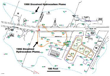
The dissolved hydrocarbon plume experienced a dramatic size reduction from 1995 to 2003 (see Figure 6). Analysis of changes in concentrations of constituents of concern over time was used to assess the effectiveness of the remediation system, and to evaluate plume stability. The slope of the natural log as a function of time describes attenuation characteristics. Decreasing concentration trends occurring both in the source area and in the downgradient plume would suggest that active remediation and natural attenuation is occurring. Increasing trends in both source and downgradient areas would indicate that the rate of contaminant loading into the aquifer exceeded the rate of natural attenuation. Plume stability is typically indicated by unchanging concentrations.
Figure 5: Separate-Phase Hydrocarbons Prior to Horizontal Well System

Groundwater contaminant concentration trend analysis demonstrated steady improvement from 2000-2005. The trend analysis reveals decreasing trends in most wells at the site, suggesting that active remediation and natural attenuation has reduced the source mass and decreased the footprint area of the dissolved plume (Figure 7). In one exception, concentrations of ethylbenzene and xylene are increasing, however, this trend does not account for high concentrations that would be in a well that was excluded from the sampling and analysis because it contains separate-phase hydrocarbons.
Conclusion
Conventional wisdom says that bio-sparging is ineffective for remediating NAPL because it is not feasible to introduce sufficient quantities of oxygen across the source mass to sustain bacteria populations that use the hydrocarbons as a nutrient source. This project proves that conventional wisdom is not always reliable. At this site, bio-sparging with horizontal wells eliminated at least 30,000 gallons of NAPL at this site. NAPL bio-sparging can be successfully implemented when applied using properly designed and installed horizontal remediation wells. A horizontal well system provide significantly greater source mass contact area and oxygen quantity compared to an equivalent system of vertical wells. Horizontal remediation well systems can be very effective and less expensive at remediating large expanse plumes than vertical well systems. In addition, this project demonstrates that horizontal sparge wells can be used as very effective barriers to plume migration.
Figure 6: Dissolved Groundwater Plume

Figure 7: BTEX and MTBE Trend Anaysis

PDF: Post-Closure Analysis Proves Success of Enhanced Hydrocarbon Bioremediation Poster