The Battelle Chlorinated Conference gave hundreds of consultants the opportunity to learn about how horizontal remediation wells are being used to overcome some of the greatest challenges facing environmental remediation professionals. For the thousands of consultants who couldn’t be there, we are sharing some of the insights that were shared as part of the event.
Below is a case study presented at the conference that demonstrates some of the innovative techniques used in implementing SVE systems.
Real-Time Data through Horizontal Soil Sampling for Optimal Horizontal Vapor Extraction Well Construction
CASE STUDY SUMMARY
The Challenge: Vapor intrusion at a manufacturing facility had impacted indoor air quality. Multiple source areas were present and accurate characterization of the contaminant plume beneath the building was difficult due to limited interior access. The consultant did not want to risk poor remediation system performance due to data gaps and site conditions which would limit drill rig access in various areas of the building interior.
The Solution: Directional Technologies provided the consultant with a plan to utilize horizontal drilling to simultaneously collect soil data and install a horizontal SVE system that could precisely target critical areas. During remedial construction, Directional Technologies used real-time field screening techniques to identify where contaminant concentrations were highest and adjust designs for the SVE system while in the field. The optimized horizontal SVE system was able to effectively address the indoor air concerns and the success of this project resulted in additional horizontal SVE wells installed at other buildings located throughout the facility property.
BACKGROUND / GEOLOGIC SETTING
Elevated concentrations of various chlorinated solvents were detected in the soil and groundwater beneath the building. Indoor air concentrations of PCE and TCE were detected above the commercial/industrial threshold value. The source area included several drain line locations associated with a former laboratory where potential releases of solvents may have occurred from the 1950s to the 1970s. Current manufacturing activity at the facility limits interior access to the building due to the configuration and layout.
In 1988, six vertical DNAPL recovery wells were installed in the vicinity of the building and were operated for an unknown period of time. PCE and TCE concentrations continued to be detected in the groundwater into the early 2000s at concentrations exceeding 400,000 ppm. Soil sampling conducted in the mid-2000s suggested that the former drain lines had leaked across multiple discrete areas, resulting in high soil concentrations in some portions of the building and low concentrations in others.
The material directly under the building is a fill consisting of sand and gravel with cobbles that overlay a native glacial till. The fine to coarse sand of the shallow overburden is characterized by medium to high hydraulic conductivity in the 30 feet/day to 50 feet/day range. Seasonally, the depth to groundwater in the shallow overburden ranges from approximately 9.8 to 13.2 feet below grade.
APPROACH / ACTIVITIES
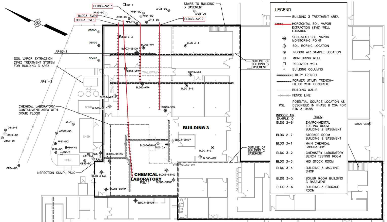
To reduce VOCs in the vadose zone and depress ambient pressure under the floor in order to control vapor intrusion into the building, horizontal SVE wells were designed and installed with horizontal directional drilling techniques. A preliminary well layout design was devised based on previously available assessment data. During the initial horizontal pilot bore of each well, soil samples were collected at 5-foot intervals and screened via PID. As the real-time soil data was collected, elements of the preliminary well layout such as screen lengths, screen interval starts, and bore alignment were revised to optimize the design.
Key Design Factors:
- Screen intervals were placed in areas under buildings where real-time data revealed the highest concentrations.
- Four total horizontal SVE wells with 30 feet to 60 feet of screen per well. Wells were 2-to-3-inch diameter and were installed 2 feet beneath the concrete floor.
- Site-specific wells screen designs; custom-engineered using Directional Technologies proprietary design software.
- Drilling was conducted via blind (single-entry) bores staged on the side of the building that would not impact facility operations.
- SVE system was designed to run at 100 CFM and was operated by a 5-horsepower regenerative blower.
RESULTS
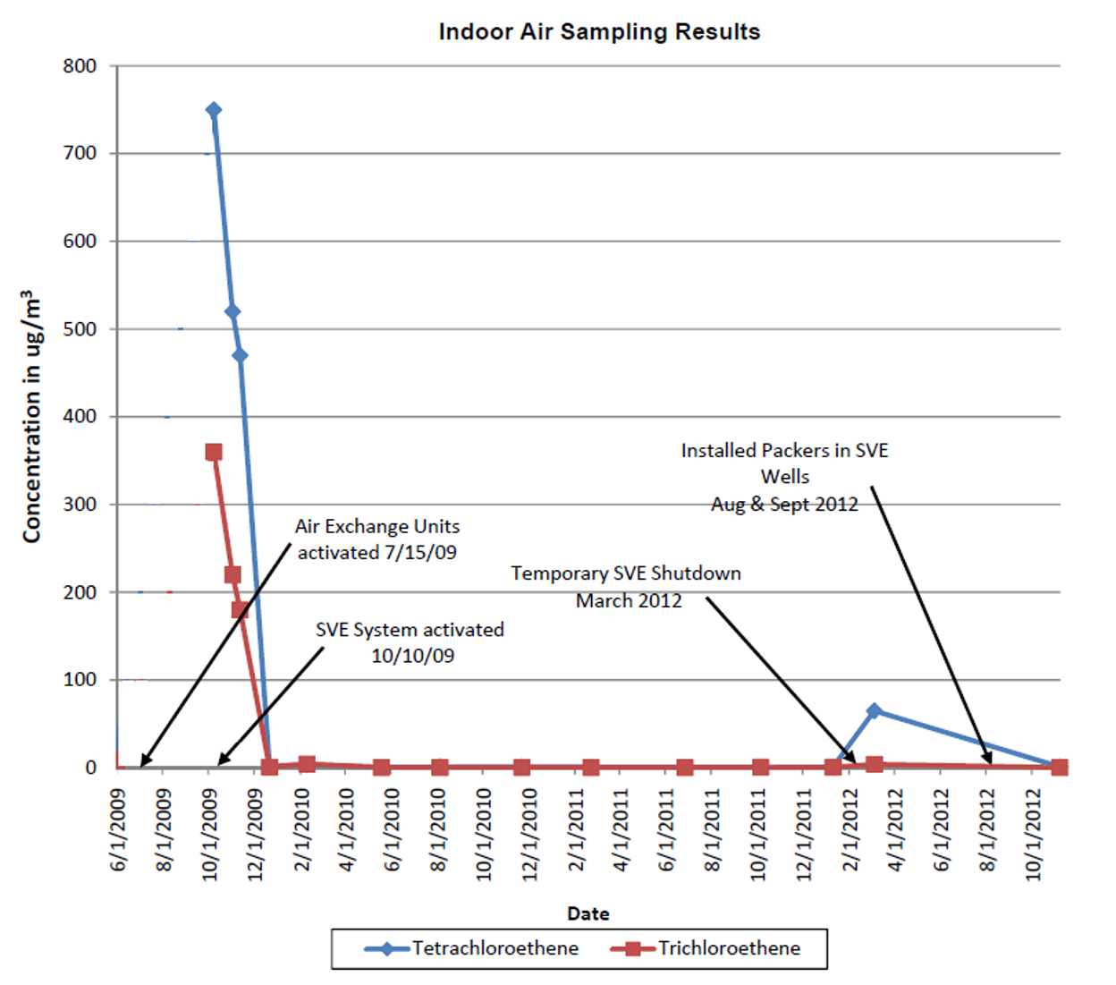
Pilot testing results indicated that each well achieved an approximately 21-foot radius of influence. The average total flow rate for the SVE system was approximately 133 CFM. The initial operation of the system resulted in a sharp decline in indoor air concentrations of PCE and TCE.
In the third year of system operation, a 20-foot-long, inflatable well packer was installed in one of the horizontal SVE wells to help focus soil vapor extraction in the area of the building where higher levels of PCE were detected. The packer installation resulted in a reduction of the exposed well screen from 60 feet to 25 feet and focused the vacuum on the shorter length of the well-screen near the affected area.
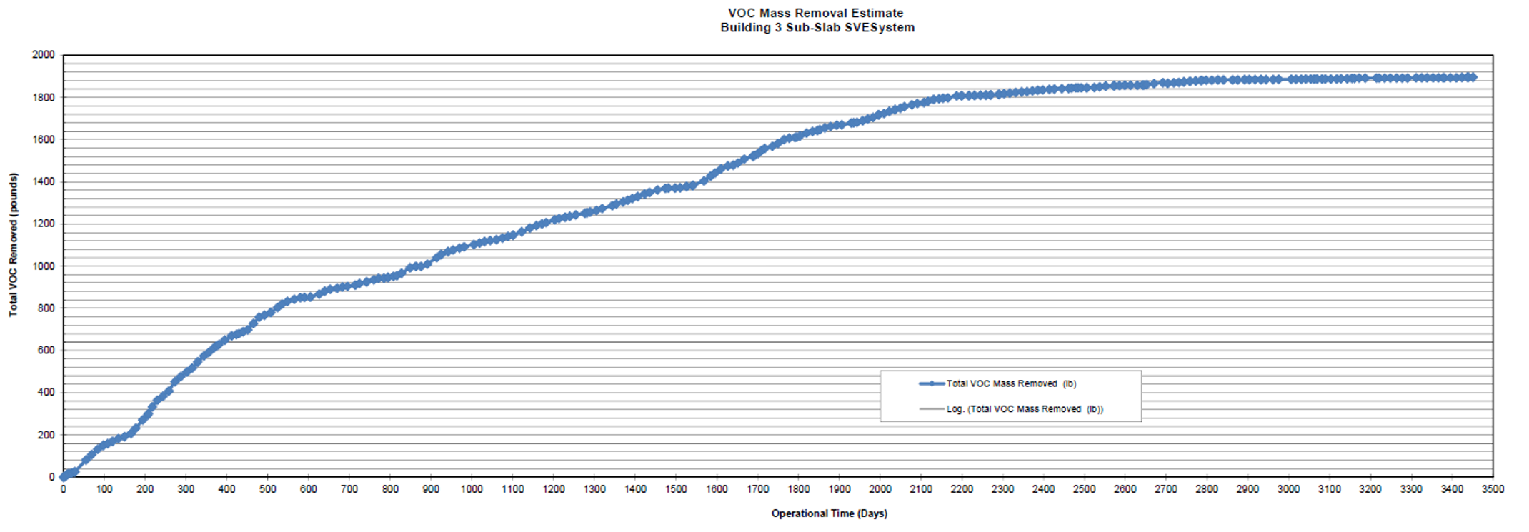
Over an 11-year period, the SVE system had removed an estimated 1,915 pounds of VOCs from beneath the building, with daily removal rates as high as 3 pounds per day in the first year of operation. As VOC concentrations reduced over the years, the system was operated as a mitigation system with an applied vacuum at all four SVE wells.
After achieving the remediation goals and resolving the vapor intrusion concerns, the system was shut off in January 2022.
Click Here For High-Resolution Poster Image
What innovative techniques could have been used on your last few SVE projects? Contact our horizontal well experts at 1-877-788-4479 or drilling@directionaltech.com to discuss your current project needs.


